
Professional Security System Installation Made Easy
How Resistors Are Used in Security System Zones
Alarm zones are nothing more than current limited dc circuits. If you were to connect a volt meter across an unused zone, depending on the make and model of alarm system, you'd read somewhere close to 12 volts. The alarm system uses this voltage to determine the status of the zone.
12 volts = There's an open circuit between zone positive and ground
0 volts = There's a short between zone positive and ground
You're probable aware that a short in an electrical circuit is a bad thing, in a normal electrical circuit that's very true. An alarm panel zone differs in that it's designed to accept a short with no problem. In fact, if end of line resistors are disabled in programming a short is exactly what the panel is looking for in a normal (not tripped) zone. If the panel see's zero volts (or close to it) it considers the zone secure. If it see's 12 volts (or close to it) it considers the zone faulted.
Resistors add an extra degree of security to the zone. Alarm manufacturers design their zones to look for a specific resistance on their circuits. Honeywell for example, uses 2000 ohm resistors on their hardwire zones. The Honeywell hardwire zone with a 2000 ohm resistor inline with it will read about 5 volts at it's terminals, so now we have:
12 volts = There's an open circuit between zone positive and ground (the zone is faulted)
5 volts = The circuit is closed with it's resistor intact (the zone is clear)
0 volts = There's a short between zone positive and ground (the zone is faulted)
By installing the resistor at the farthest device on the zone (the "end of line") you create a supervised circuit that can no longer be disabled by simply shorting it's wire somewhere along the wire run between the control panel and detection device.
Hardwire Zone EOL Resistor Status
5 Volts


Zone
Com
2000 Ohm Resistor
Closed Contact
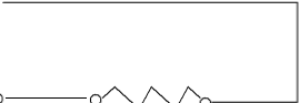
This circuit has a continuous path through the closed contact, the alarm panel will be able to "see" it's 2000 ohm resistor. The zone will show normal on the keypad (not faulted.)
Normal Zone
12 Volts


Zone
Com
2000 Ohm Resistor
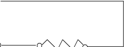
Open Contact
Faulted Zone
This circuit will show faulted on the keypad because the contact has opened, breaking the circuit to the 2000 ohm resistor. If the system were armed when the contact opened the system would go into alarm. This is exactly how a motion detector or door/window contact triggers the zone.
0 Volts


Zone
Com
2000 Ohm Resistor
Closed Contact


Faulted Zone
This circuit shows a short across the 2000 ohm resistor, the zone will fault if unarmed, or sound the alarm if armed. The reason alarm resistors are called "end of line" resistors is because by placing the resistor at the end device (motion detector or door/window contact) the circuit can be monitored for shorts in this manner.
Resistor Facts
Learn more about security system installation by visiting the main page.
- Resistors have no polarity.
- Their color bands specify their resistance values and percent tolerance.
- They're not proprietary, so you can run by Radio Shack and stock up if you want.
- Their resistance's will add together if wired in series (two 1000 ohm resistors = 2000 ohms)
- Resistors routinely use "K" to represent 1000 (a 2000 ohm resistor = 2K ohm resistor)
Learn more about security system installation by visiting the main page.
J.L. Metcalfe is a participant in the Amazon Services LLC Associates Program, an affiliate advertising program designed to provide a means for sites to earn advertising fees by advertising and linking to Amazon.com.
MyAlarmGuy.net